Today I thought I'd simply whip off those levelers and then move on to all sorts of other tasks. The levelers however were not cooperative with my time estimation. Crap - how long could a few levelers take fer gawd's sake?! Well, most of the day actually, and I took a bunch of photos. So many photos in fact I have decided to run right past my normal 15 picture limit for this post. If you have a dial-up connection, my apologies.
First task was to identify which way the grain runs in the chunk of Gabon Ebony I have. This is not easy - but with a fresh cut off of one end, and good natural light, the growth rings are just barely visible:

I chose to orient the rings for these leveler feet on the vertical grain, so as to minimize their movement in service.
I did some drill press work, two cutters involved, and had the levelers defined on the stick of ebony:

A run through the band saw to separate them:

I must be getting lucky or something, as the target dimension of 0.5000" for these pieces was virtually achieved right off the band saw cut:

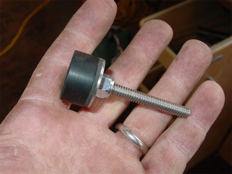
So here's the hardware I have cobbled together for these levelers:

Stainless 1/4" bolt on the right, ebony leveler foot, neoprene washer, stainless fender washer, and nyloc nut.
One of the two steps on the drill press was to establish counter-bores for the stainless bolts:

Then I needed to mortise the end of the legs to receive the ebony leveler pads. I used a circle jig with my router to sink a hole into some MDF, then used a trimming bit to clear the hole out:

Here's a view of the leveler foot snugly tucked into the routing template:

Then I marked out the end of the leg for the mortise - a Starrett carpenter's compass with a 0.3mm mechanical pencil attached was used to mark out the circular mortise line:

The template was to mount onto a support bracket, which I also made of MDF, using a tongue and groove to locate the pieces to one another:

A pilot hole is drilled into the end of the leg:
Then I place the metal center-point from my circle routing attachment directly into the leveler foot, which had an internal hole made precisely the size required to accept that center pin:

That assembly is then pushed onto the pilot hole on the end of the leg:

That centered leveler foot on the leg now becomes, prest-o-change-o, a centering bushing to locate the MDF mortising template:

I countersink and fix screws to hold the template to one side of the support bracket. Then I double check the interior is square before affixing the other screws:

Once the jig was assembled up, I used two routers, one to rough plunge and one to trim, to complete the first mortising step:

The other three legs were then done, however the pilot hole step was omitted as I allready had the mortising jig calibrated. Still, I had more work to do in these holes, so I used a over-sized ebony plug as a guide bushing to center a transfer punch:

Tap! and the center punch makes its mark:

The result:

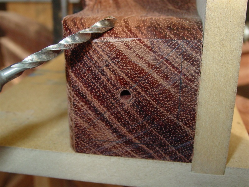
Next step was to chuck a 3/4" Forstner bit into my cordless drill and establish a second counterbore inside the mortise. A fine plan, however the Forstner bit made about as much progress into the bubinga end grain as if I were drilling titanium plate. So, onto plan 'b' - I drilled a 4mm hole on the dimpled center mark, then used a 19mm Star M auger bit to plow out that second counter-bore. The 4mm hole centered the bit without letting the auger's lead screw get too enthusiastic, if you, ah, catch my drift....
With the second counter-bore done, I decide to check out how a t-nut would drive into end grain bubinga, so I made up a piece to check:

No problem as it turned out.
Next step was to clearance the second counter-bore for the t-nut and 1/4" screw shaft:

Then I used a 18mm long socket as a drift and a hammer to drive the t-nut into place:

Back to the hardware. The neoprene washers are intended to give the leveler feet a little cushioning against impact shock (if the table were to be set down or dropped onto a harder surface, for instance), and to allow a little side to side play for the leveler pad. I used some permanent double stick carpet tape to attach the neoprene washers to the stainless fender washers:

Peel the backing off and press the two together and voila!:

Next I dealt with the leveler feet again. I grabbed a piece of 320 grit sandpaper and spritzed some camellia oil onto it:

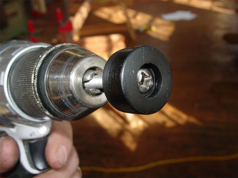
Then I used my drill, with one of the 1/4" stainless bolts as an impromptu arbor, to smooth and polish the feet a bit:

It doesn't take too long to buff them up quite nicely:
Assembly time!:
This process took ages and I was starting to get a bit worried about how long this 'simple' process was taking, however when I attached the leveler to the leg, any concerns evaporated:

These leveler feet were worth every hour of time I put into them:

All the way in, they just protrude 1/32" from the bottom of the leg:

So, I hope the surfeit of pictures today goes some distance toward explaining why the leveler feet took more time than anticipated. After they were complete, I went on to finish off the profiling work on the legs and patched the small bit of tear out from yesterday. I'll save those pics for next time. All in all a decently productive day. I'm nearly over my cold, so look out world!
Thanks for coming by the Carpentry Way today. On to post 37
Genius! I'm really enjoying this build.
ReplyDeletewell done! nothing like some Canadian ingenuity on ancient Chinese!
ReplyDeleteWell done Chris. Good use of your Makita drill. I really like mine although I have blown up third gear for the second time. If there is room in my next projects maybe I will spring for a Festool. Hmmm. The fit and finish on your levelers is exceptional. My question though is when the table is completed I imagine it will weigh a great deal. How easily will your client be able to lift the table to get a philips underneath to make adjustments? I just completed a table for a client roughly the same dimensions but in rustic alder. I added my levelers just as you did but then realized that to operate them would be to difficult so I had to cut small notches (large enough for fingers) for my client to adjust out the wobble without resorting to two men and a boy for help.
ReplyDeleteThank you for the extra detail,
John Deerman
Thanks for posting this Chris, this really is wonderfully useful for transportable furniture.
ReplyDeleteAdam,
ReplyDeletevery kind of you. I hope the build continues to hold your interest as there are a few posts to go yet.
gderamel,
thank you - one of the rare occasions perhaps where Canadians can affect world geopolitics by way of furniture.
John Deerman,
the table is not as heavy as I suspect you may be estimating. I have done 'things' to lighten the table, and more steps in that regard are to come. I am thinking it will weigh around 100 lbs. As far as adjusting the leveler, that shouldn't need to occur too often, and I'm confident that it won't present an undue hassle for the client.
I'm not so sure about the Festool drill - had one a while back and the batteries did not impress, so I sold it. They have neat accessories though. I haven't had any problems with my Makita so far, however if there drilling job is more onerous, I pull out a corded drill, or use the impact driver.
Kane,
I appreciate your comment - thanks!
~Chris
Found this 2 1/2 years after the initial post, so not sure you will even see this. If you build levelers again, socket head cap screws are nice. Only have to lift the table the height of an Allen wrench. Reading this in Shanghai, found the blog while looking for a similar table. really, really nice work.
ReplyDeleteJohn Beutell
Hi John B,
Deletethanks for your comment and hey, good idea! That would be convenient to have an Allen head cap screw or maybe Torx for that, especially if the table was a piece that was moved around a lot. In this case the table stays where it is all the time, but I'll keep that idea in mind for projects involving smaller pieces in the future.
~C