A couple of readers have commented about having problems rendering or using the arcs I show in the drawing - welcome my friends to SketchUp, and the problem it has with representing curves and attaching lines to curves. It's frankly one of the shortcomings of the drawing program, and has given me my share of hair-pulling moments of frustration at times.
In SU, there are two ways to draw a circular line - either one uses the 'arc' tool or one uses the circle tool and then chops the circle up into the required arc portion required. Either way, SU is representing that circle as a series of facets. If, at the tangent point to the arc, there happens to be a facet arris, then the point is slightly further out than where it ought to be. If one is, on the other hand, connecting to a facet more closely to the midpoint of a facet, then the point is further in than where it ought to be. One can specify that either the circle or the arc tool have more facets, up to 1000 facets I think, but then it is still hard to know where the tangent point of the circle is located. One can download plug-ins to deal with this, like True Tangent, but in the end, it really is simpler and easier to draw an arc with an old-fashioned drawing compass than SU. Shocking, I know.
On this charpente problem drawing I am presenting in this series, while I am using SketchUp, I am not presuming that the reader is also using it - in fact I am presenting the material in such a way that the reader with pencil, straightedge, compass and rule can accomplish the drawings. Readers who are following along with SketchUp, and who are unfamiliar with its peccadilloes in terms of arcs and circles may run into little errors when trying to connect to arcs. The arcs on my drawing are in fact only representational, and the lines that purport to connect to them, actually do no exactly connect to them. Its fiction actually. I figured out the positions of the lines using a little bit of math.
Here, I'll show you what I mean - in this next picture, I have placed a large arrow pointing to the intersection of an arc and the line which it is supposed to delineate:

Now I'll zoom right in on that arrow, and you can see that the faceted arc does not exactly meet the line:

In the above picture it almost looks like the facet arris of the arc actually does meet the line a little lower down from where the arrow points, however if you zoom right in you will see it does not in fact intersect:

The line's position is determined not by the arc, which I know to be wrong, but by using a little math. The cross sections of the sticks, which are square, each measure 20 cm on a side. The diagonal of that square is √2 times longer, that is 20√2, which equals 28.2842712474619... or thereabouts. The distance therefore of the bottom line of the stick (in the elevation view) from the top line of the stick is 28.2842712474619... and the line in the middle is 1/2 of that, or 14.142135623731... roughly. That's how I spaced the lines on the elevation view of the stick, not by using the arcs on SketchUp.
Alright, on with the fun - in the last blog entry in this series we formed a large plane off of one of the surfaces of stick 'a', like this:

We then noted how that plane meets the floor and forms a line emanating from the foot of the stick, and with a few magic tricks we produced the following lines on the elevation view of stick 'b', showing where the plane from stick 'a' intersects it:

Today we are going to do pretty much the exact same procedure, this time with another plane. The simplest one to consider is the plane formed by the surface of stick 'a' which is parallel to the surface we already played around with. That surface can also be extended into a plane, just as we did before, and this time I'll make that plane light green in color:

It may not be clear that the green plane formed by that rear face of stick 'a' even intersects with stick 'b', however if we swing around to look at things from the other side, it is clear that is does intersect:

So, just like we did in the previous post, I'll disappear that green plane, only to leave its trace upon the floor, a line which runs roughshod over the plan view of stick 'b' at slope:
And, just like with the work we did on the orange plane's ground trace previously, here we not the intersections of the green plane's trace line with stick 'b''s plan, and mark those points as 5, 6, and 7:

Moreover, from 5, 6, and 7, we then project square to the axis of stick 'b''s plan, traveling over to the ground line of stick 'b' in elevation view. We label these intersections 5', 6', and 7' respectively.
Now, since this green plane is parallel to the orange plane we used in the previous blog post, one would think that all lines generated from the green plane's trace would also run in parallel to the lines from the orange plane's face, no? Therefore, if this is true we can run lines up from 5', 6', and 7' up parallel to those lines previously marked out for the orange plane, that the lines that gave us the points 1", 2", and 3":

You can see in the above illustration that from our points 5', 6', and 7', we have run lines parallel to those previously generated, to form new points of intersection, namely 5", 6", and 7". If you're a little confused as to why 5", 6", and 7" are points that require marking, and not other places where the lines cross, take a look again at which lines in the plan view of stick 'b' we crossed originally, giving those first points of 5, 6, and 7.
Here's a closer view showing our new points, the entire point of today's drawing exercise, 5", 6", and 7", formed in much the same pattern as 1", 2", and 3":

Just as before, since the line crossed in plan where we obtained the crossing point labeled 6 was actually the top and bottom arris of the stick, it should come as no surprise that when this line is projected across the elevation view of the stick we would obtain two points of intersection, one on the bottom arris and one on the top.
Now then, in case the reader might not be sure of my assertion that these lines we have generated to points 5', 6', and 7' are to run parallel to the lines we obtained from points 1', 2', and 3', let's just confirm that geometry. You may recall that the way we obtained the slope line crossing the elevation view of stick 'b' was produced by two points. The one at the bottom was the intersection with the trace at point 3, which projected to give point 3', and the point at the other end was found by projecting a line from the top cut view of the stick and meeting the same arris as 3 was marking further down. We should be able to replicate that exact procedure, no?
Here's the projection then of the other side of the top cut of stick 'a':

Notice on the right side is that projection line which met the arris of stick 'b' (plan view) at point 4. We have now projected a line from the other side of that white diamond indicating the top cut, and this meets the arris of stick 'b's plan at point 8.
That line at point 8 then projects at a 90˚ angle to the plan axis of stick 'b', and travel up to the line representing the plane of the top cut of the stick, in elevation, to give us point 8':

Notice that at point 8', the line from point 7, via 7' and 7" drops right in to say hello. Thus we confirm the geometry of that slope, and know that in future we needn't bother with such confirmations when parallel faces are involved.
So, another fine mess we have created here:

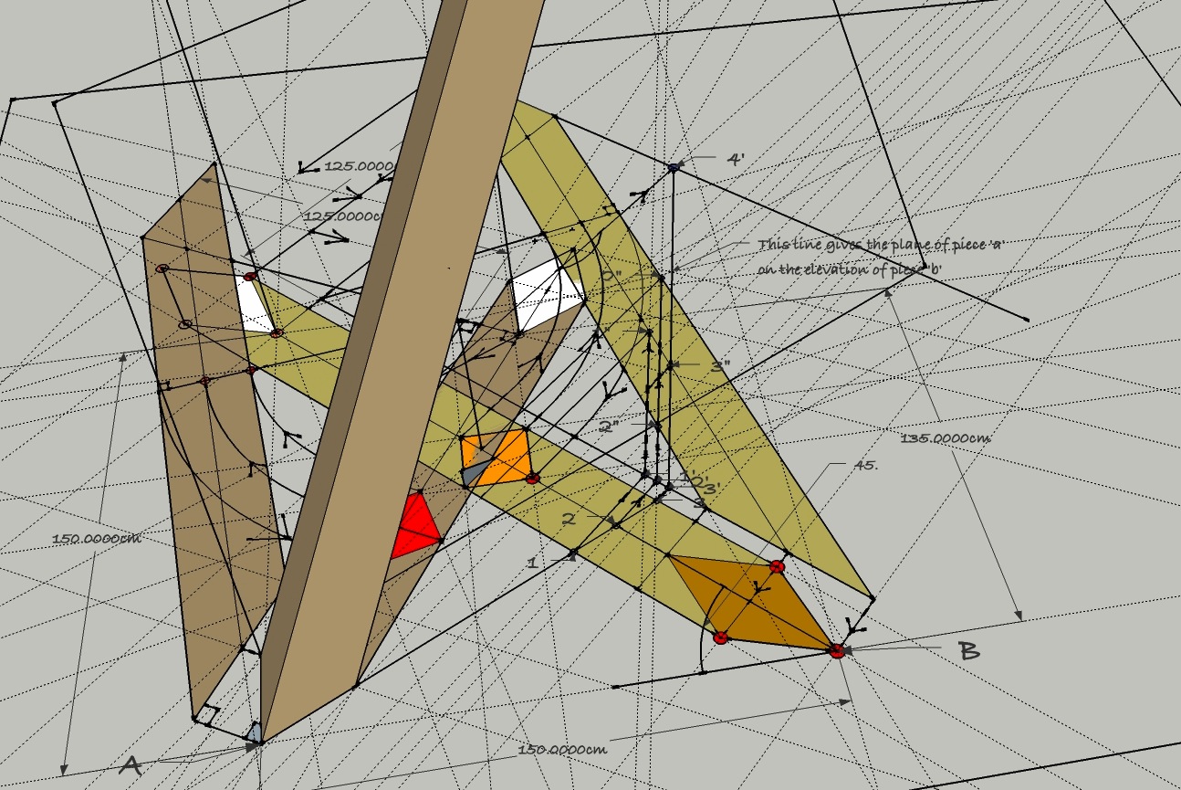
Where's it all going? If we look at a view from the rear side, we can hopefully gain some clarity about what has been accomplished so far:

Today we merely repeated what we had done in the previous post, and by using a face which was parallel to the one dealt with earlier we made this pretty much a paint by numbers session. In the next post, we will move yet closer to our objective as we deal with the remaining two planes on stick 'a'. Enterprising readers may wish to forge ahead on their own if they feel confident as to the methodology.
And if you are thoroughly confused, swimming in lines that have lost all relevance or meaning, well, sorry if I managed to confuse anyone. I'm trying to be as clear as I can in my explanation, but I'm sure it could always be improved. As you learn, I learn.
All I can say, is if you feel like you're stuck in the muck, simply start a new drawing and work through the steps again in this series - and again if necessary - until simply be rote copying of what I have illustrated thus far you produce the same drawing. You will find that each time you re-draw you will gain a clearer understanding, if not basic familiarity with what is going on.
Thanks for dropping by the Carpentry Way today. --> go to post 8
No comments:
Post a Comment
All comments are moderated. Spamming and comments containing links unrelated to blog content will be deleted.