I needed to make a trip out to New York state yesterday to the CNC sub-contractor, as there was a glitch in the cutting which resulted in an odd appearance on the lower front face of the sticks where they met at a miter. This problem had showed up after two test pieces had been cut and placed together:

Note how the lower surface turns inward rather too abruptly. This is due to a peculiarity in the geometry of the piece, something that in the design phase I had struggled to render properly in SketchUp, which is poor when it comes to manipulating curvilinear forms. At the CNC place, they had Autocad, so I was able to sit down with a programmer and make the necessary tweaks with relative ease.
Then I spent most of the afternoon there as the pieces were milled up in a series of steps. The milling is done on top of an MDF fixturing jig, which is milled out by the CNC so that vacuum can be used to hold the piece down. To aid in that, a groove is milled so as to take a rubber gasket:

In addition, small squares of adhesive-backed stair tread grip tape are affixed around the points where the vacuum is pulled so as to allow the vacuum to reach a wider area of the underside of the piece:

Further, a couple of dowel-locating holes are drilled, both in the jig and in the pieces to be worked, so that after several passes are done to produce the front face profile, the piece can be flipped upside-down and located to the exact same position for the cutting work in the inside curve portion.
Here's the profiling cutter in action:

It's an insert-knife shaper cutter running on a 3/4" spindle. I noted that they buy their shaper tooling at the same place I do. The CNC makes the above cut a lot safer proposition, and gives a smoother result, I do believe, than if I were to have made a fixture to template-shape the piece in my shaper.
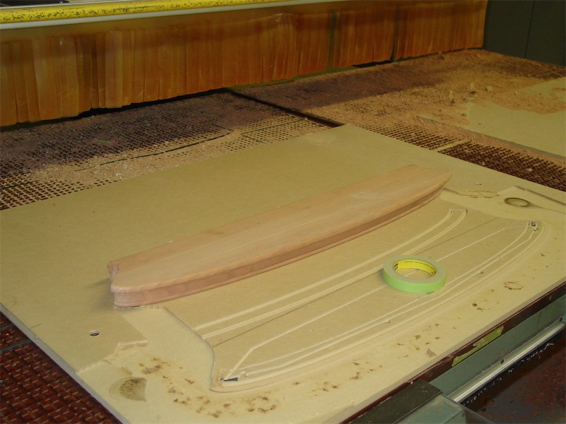
Here's a look as the front face profile is nearly complete:

The gantry then moves out of the way, the table automatically moves forward, and then the operator uses an air line to blow the shavings off. Here's the piece after the front face profiling is done and the piece has been flipped and re-set in the jig in preparation for milling the rear face, where the vacuum also holds the piece firmly in place:
The cutting on the rear face employs a multi-step process. First a series of passes are made of increasing depth:

Then, once the cut is about 3 mm from going through the bottom of the piece, another cutter is brought in, this one taking a final cleaning pass about 0.003~0.004" further in.
At this point, the piece is done as far as the CNC cutting goes - the vacuum is then cut, and the piece removed from the fixture:

At the top of the above photo you can see that this CNC machine has two tables and each moves independently of the other. The upper table has a fixing jig similar to the lower one, except it is for milling the short side table top frame pieces on this job.
Here's a look at the two short side pieces after cutting is complete:

I was pleased with the result. The cutting was quite clean for the most part, with only a modest amount of chatter marks left in a couple of spots where the cutter was working most strongly cross-grain. These two pieces above only had a slight amount of material left on their inside corners to guard against tear-out, and it was actually adequate. For the long side pieces though I had them change the program slightly to add even more material to those spots. Call me paranoid. I'll hand-dress these areas down to sharp irizumi ('re-entrant') points later on.
Back at the shop I used the bandsaw to sever the support sections away, leaving me with the four frame pieces:

The long and the short sides, one of each I mean, are abutted in the next few shots so as to show how things look:

With the pieces upside-down on the table, here's a closer look at the two frame members coming together:

There were very slight discrepancies here and there where the two face profiles meet, but it will be a very straightforward procedure to file and smooth that interface to give a clean look.
A look now with the pieces right-side up, looking at the inside-corner:

Here, the difference in the amount of material left at the re-entrant corners on each piece is very apparent. I leave myself more filing work to do on the one with the extra chunk left in place, but better that than risking tear-out in that location from the routing. In the above picture I have not cleaned the remaining material from the bandsaw cut, but again, a simple matter to take care of. A good fit between pieces I think, and the rebate for the glass piece is exactly the same depth on each. Nice!
Finally, a look at the front profile where the two pieces come together:

Compare this picture with the first one in the post showing the test pieces and I'm sure you will agree the appearance is much improved in regards to how the lower portion of the profile comes together. It was good to take the trip to see the process firsthand and work with the programmer to solve the issues.
Next up with these pieces are the cross-splined, draw-barred and wedged locking joints, and before I can start that phase I have a couple of fixturing jigs to make. The legs are due to enter the world of 5-axis CNC cutting by the end of the week, so they should be in my hands within the next 7 days or so. More to come in this thread, so please stay tuned.
Thanks for dropping by the Carpentry Way. --> on to post 9
No comments:
Post a Comment
All comments are moderated. Spamming and comments containing links unrelated to blog content will be deleted.